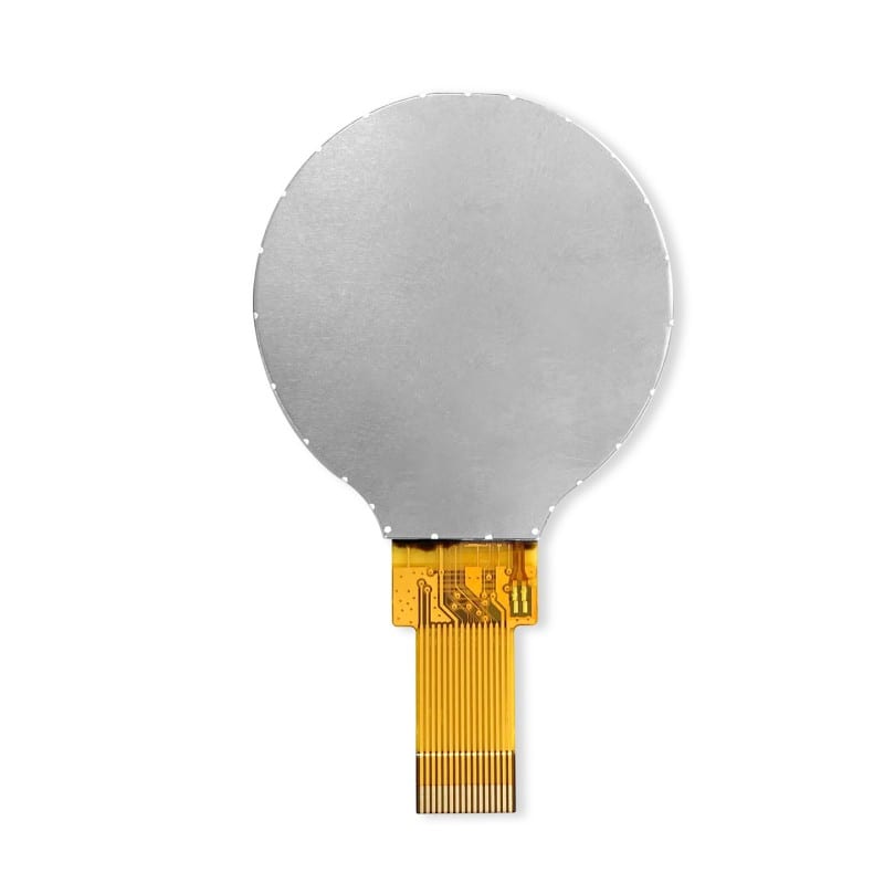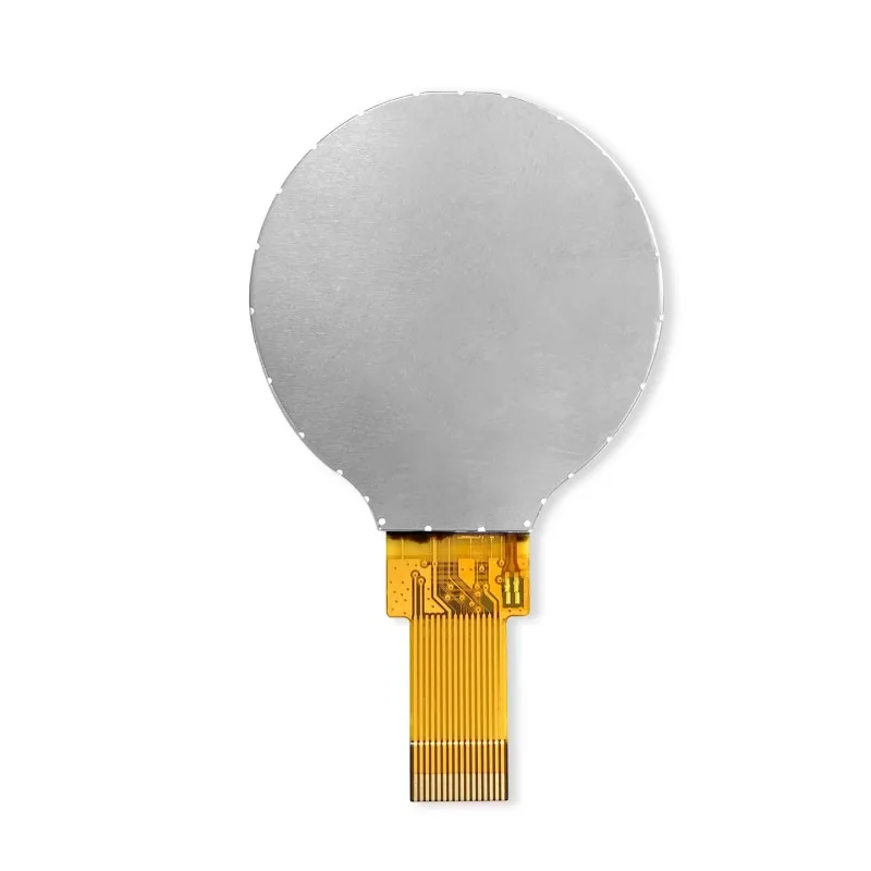
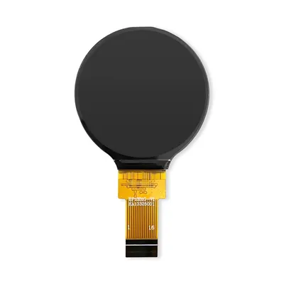
EP1331G 1.28-inch Round TFT LCD Display 240x240 SPI

1.28" 240x240 SPI

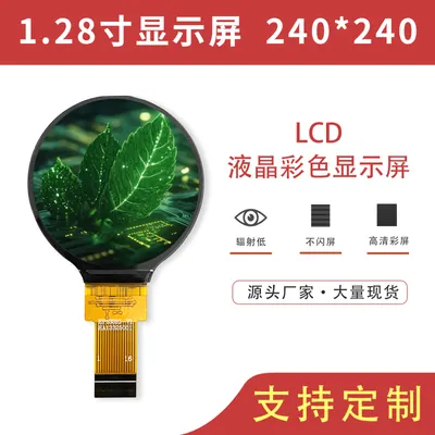
The EP1331G is a 1.28-inch round IPS display with a full viewing angle, 240×240 resolution and RGB565 data format, driven by the GC9A01 controller over a 4-wire SPI interface, with a full iron frame for protection.

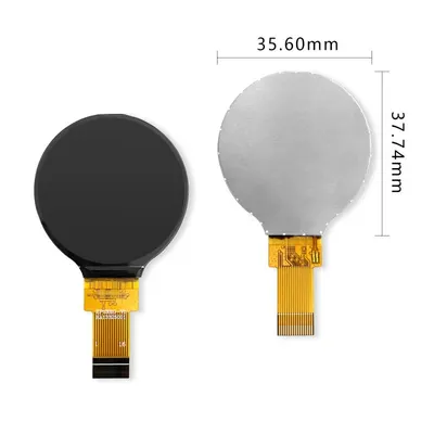
Outline 35.60 × 37.74 × 2.2 mm, active area 32.4 × 32.4 mm, pixel size 0.135 mm, 16-pin FPC on 0.5 mm pitch with a plug-in connection. Operating temperature -20 to 70 °C, storage -30 to 80 °C, RoHS compliant.

ModelEP1331G
Size1.28 inch
Resolution240x240
Interface4-wire SPI
Driver ICGC9A01
Viewing angleFull viewing angle
TouchNo
Pin count16pin
Pin pitch0.5mm
ConnectionConnector
Outline (W×H×T)35.60 (W) × 37.74 (H) × 2.2 (T) mm
Active area32.4 (W) × 32.4 (H) mm
Pixel size0.135 (W) × 0.135 (H) mm
Data formatRGB565
Operating temperature-20℃~70℃
Storage temperature-30℃~80℃
Backlight2 white LEDs in parallel
Brightness400cd/m²

Category: TFT LCD Displays & Modules
Documents

Documents & driver code

ETMCU projects are Keil-based; ESP32 projects are ESP-IDF and include LVGL.

ETMCU board · Keil project

Complete build-ready projects including driver code, schematics and examples. Need an interface that is not listed? Ask our engineers.

Specifications

Detailed specifications

What these numbers mean
  • 400 cd/m² luminanceClearly readable under normal indoor lighting; choose a high-brightness model for direct sunlight or outdoor use.
  • 4-wire SPI interfaceFew pins and simple routing, suited to small and medium sizes with limited host resources; use RGB / MIPI for high-resolution larger panels.
  • 240×240 resolutionGood for icons, gauges and simple UI; not intended for text-dense or multi-column layouts.
  • Operating temperature -20 to 70 °CCovers most indoor and general industrial environments; choose a wide-temperature model beyond that.
  • TouchThis model has no touch panel; choose a touch model or request customisation if you need touch.

Basic description

ItemSpecification
Product name1.28 inch IPS full viewing angle high-definition display
Display modeTransmissive
Display format240 x RGB x 240 dot matrix
Data formatRGB565
Colours65K colours
Interface type4-wire SPI
Viewing directionFull viewing angle
Driver ICGC9A01
ConstructionFull iron frame protection

Mechanical specifications

ItemSpecification
Outline dimensions35.60 (W) * 37.74 (H) * 2.2 (T) mm
Resolution240 RGB * 240 dots
Active area32.4 (W) * 32.4 (H) mm
Pixel size0.135 (W) * 0.135 (H) mm
  • The thickness given for the outline dimensions excludes the FPC and double-sided tape.
  • Drawing tolerance note: GENERAL TOLERANCE ±0.20

Electrical & environment

ItemSpecification
IO voltage IOVCC1.8–3.3 V
Analog voltage VCC2.8–3.3 V
Operating temperature TOPR-20°C to 70°C
Storage temperature TSTR-30°C to 80°C
Environmental complianceROHS
  • IOVCC and VCC may be tied together and powered from a single 2.8–3.3 V supply.
  • When VCC is 3.3 V, VCC, IOVCC and LEDA (backlight anode) may share the same supply rail.
  • Module_VCC is the display power supply pin; LCD_IOVCC is the I/O power supply pin.

Brightness & power

ItemSymbolMinTyp.MaxUnit
LED backlight forward voltageVLED2.93.03.1V
Per-LED typical currentIF-15-mA
Total backlight currentILED-90-mA
Display surface luminanceLS-400-cd/m²
LED backlight uniformityLD80--%
Total display power consumptionPLCD-0.386-W
  • PLCD = VCC × ILCD + VLED × ILED.
  • The backlight uses 2 white LEDs connected in parallel: 15 mA typical per LED, 90 mA typical in total. A current-limiting circuit (typically a resistor of about 4.7 Ω) is required; overheating from prolonged operation can permanently damage the display and backlight.

Response time & contrast

ItemSymbolConditionMinTyp.MaxUnit
Response timeTr+Tfθ=0°-3035ms
Contrast ratioCRθ=0°-1200--

Viewing angle

DirectionConditionMinTyp.Unit
12 o'clockCR≥107580deg
6 o'clockCR≥107580deg
9 o'clockCR≥107580deg
3 o'clockCR≥107580deg
  • The 3, 6, 9 and 12 o'clock directions follow the conventional clock-face definition. The viewing angle is at its maximum in every direction, with no dead zone.

Pin definition (16 pins / 0.5 mm pitch)

1 Module_GND Display ground
2 LCD_IOVCC Display I/O power supply, 1.8–3.3 V
3 LCD_SPI_MISO SPI serial data output
4 LCD_TE Frame sync signal for camera synchronisation; leave floating if unused
5 LCD_SPI_MOSI SPI serial data input
6 LCD_SPI_DCX Command/data select: DCX=1 selects display data or register parameter; DCX=0 selects register command
7 LCD_SPI_SCLK SPI serial clock
8 LCD_SPI_SS Driver IC chip select, active low
9 LCD_RST Display reset, active low
10 Module_VCC Display power supply, 2.8–3.3 V
11 ~ 14 NC No connection (all four pins unconnected)
15 Backlight_LEDA Backlight anode, 3.0–3.3 V, typical 3.1 V
16 Backlight_LEDK Backlight cathode; connect to ground through a current-limiting resistor when dimming is not required
  • A current-limiting resistor must be fitted on the backlight anode or cathode; overheating from excessive current permanently damages the display.
  • Whether in parallel or SPI serial mode, display data is always transferred MSB first.

Reliability test

No.Test itemTest conditions
1High temperature storage80°C × 120 hours
2Low temperature storage-30°C × 120 hours
3High temperature / high humidity storage60°C × 90%RH × 120 Hrs
4High temperature operation70°C × 72 hours
5Low temperature operation-20°C × 72 hours
6Thermal cycling storage-20°C (30 min) ~ 25°C (5 min) ~ 70°C (30 min), 10 cycles
  • After a reliability test the display must rest at room temperature for 2–4 hours before power is applied, otherwise it will be permanently damaged.
  • After each test the samples must show no bubbles in the module, no seal loosening, no non-display, no missing lines, no glass breakage, and Idd no greater than twice its initial value.
Highlights

Highlights & Applications

Key features

  • Round active area — suited to knob displays, gauges, wearables and decorative formats
  • IPS full viewing angle: 75–80° in all four (3/6/9/12 o'clock) directions with no dead zone
  • 400 cd/m² surface luminance, 1200:1 contrast and 30 ms response — clear indoors
  • SPI interface with the widely used GC9A01 driver; abundant reference material and sample code
  • Full iron frame gives better mechanical strength and assembly consistency than a bare panel
  • Customisable: luminance, touch, FPC length and pin definition, cover glass and bonding

Typical applications

  • Smart-home knob displays, thermostats and central control panels
  • Round display UI for wearables and portable instruments
  • Appliance front panels in knob or dial form
  • Round indicators on industrial instruments and handheld devices

Not sure whether it fits? Tell us your environment and host platform and an engineer will confirm.

Ordering & Support

Ordering & Support

Lead timeStandard models ship in 3–7 days from stock; custom models take 7–15 days for samples; volume orders are scheduled on confirmation
MOQStandard models support small trial batches; custom projects depend on tooling and material commitment
SamplesSamples available for standard models; custom samples take 7–15 days
CustomisationSize, resolution, luminance, interface, touch (capacitive / resistive), FPC length and pin definition, construction (posts / iron frame), cover glass and bonding, firmware and UI
CertificationNational High-Tech Enterprise · ISO9001 certified · CE / FCC / RoHS reports available on request
Technical supportSchematic review, timing confirmation, driver debugging and UI development support; datasheets (PDF) and driver code published on most product pages, with schematics included in the example projects
PackagingCustom blister trays with foam separators between trays; units per carton are determined by the size and shape of the product. Thick foam protects every side inside the carton, suitable for long-distance transport and repeated handling.
WarrantyOne-year warranty to industry standard. Our quality and after-sales team analyses every defective unit: where the cause is ours, we correct it in subsequent production so it does not recur.
Long-term supplyLong-term supply commitments available for industrial projects, assessed against the product lifecycle
ExportExporting to Europe, the US, Japan, Korea and Southeast Asia; we can help arrange international logistics and export documents
FAQ

Frequently asked questions

Do you support customisation and samples?

Yes. EYA is our own factory and can customise size, interface, luminance and touch, and we provide samples.

What is the MOQ and lead time?

Standard models ship in 3–7 days from stock; custom models take 7–15 days for samples. Please contact sales for volume orders.

Can you provide datasheets and driver material?

Datasheets (PDF), driver code and complete example projects (schematics included) are published on most product pages and can be downloaded directly. For anything not listed, tell us the model and we will send it.

What certifications do you hold?

ISO9001 quality management certification and National High-Tech Enterprise status; CE / FCC / RoHS reports available on request.

Drawings

Mechanical drawings

Outline dimensions, side views and pin definitions. Click to zoom.

Outline dimensions

Related models

EP13801L

1.38" · 240x240

Same resolution

Z144SN005

1.44" · 128x128

Same interface

JLT1505A

1.54" · 240x240

Related model

EP1531S

1.54" · 240x240

Related model

Want to compare other models?

All 1.28" models → Search same size → Compare in selector → All products →